1.1
The
LARSON-SEKANINA filter
This is the
most used filter for the morphological study of comets. It was for the first
time presented by Z. Sekanina and S. M. Larson in 1984 in an article of the
Astronomical Journal. In those years there were only some basic techniques to
detect the directional gradient of brightness (GRADIENT FILTERS, see pag. 34); these techniques were insufficient because they analyze a
single direction of the brightness variations.
Steven M.
Larson of the Lunar and Planetary Laboratory in Arizona and Zdenek Sekanina of
the Jet Propulsion Laboratory in California conceived a new algorithm which
allows the application of derivatives on any direction through a simple
transformation of coordinates.
 With respect to a Cartesian system
of coordinates, a digital image can be represented with a bidimensional
function I(x,y).
With respect to a Cartesian system
of coordinates, a digital image can be represented with a bidimensional
function I(x,y).
In a system
with polar coordinates we can describe the same function as B(r,q) where r is the distance from the origin
and q it is the angle between the point
and the x axis. The origin of this new system of coordinates is no longer the
pixel of coordinates (0,0) but a generic pixel of our choice that we will point
out as (x0,y0).
A system in
polar coordinates is more convenient when the objects inside have a polar
symmetry, as the comas of the comets. In this case we assign the point (x0,y0)
to the nucleus of the comet.
The
algorithm of Larson-Sekanina can be written as:
![]()
In the
formula, from the original image B(r,theta), doubled for convenience, we
subtract two images which are geometrically modified with a radial shift of -r
and a rotational shift of +q and - q .
The result
image will lose all the possible photometric information, but it will reveal
the hidden variations of brightness inside the coma. It is interesting to
outline that these elaborations appear very similar to the sketches drawn by
the most experienced visual observers.
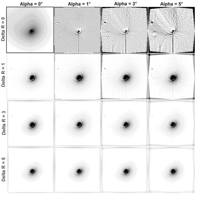
The amount
of the shifts r and q is empirically established with
some tests and they greatly depend by the experience of the analyst. Sometimes
it is also possible to reveal artifacts that don't correspond to any
morphological characteristic of the comet.
Dr = 0. The
equation of the filter becomes:
![]()
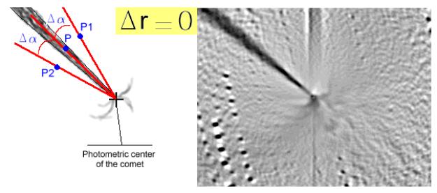
In the case
of zero radial shifts, we increase the contrast of all those details that have
an gradient of brightness with respect to the origin of our polar system of
coordinates (the false nucleus); these enhanced details are generally jets erupting
from the nucleus. In the figure it's evident the principal jet that arise from
the origin of the tail and crosses the whole quadrant to the up left corner of
the image. This gradient, calculated in correspondence of the points P-P1 and
P-P2, has enhanced the contrast of the main jet arising from the nucleus of the
comet, while on the other side of the coma it allows to glimpse some weak
fountain structures that would also be able to originate from points with
elevated activity on the surface of the nucleus.
The same
gradient has however also pointed out a defect of the CCD: the two vertical
lines in the superior and inferior part of the image are in fact due to an
smearing effect caused by the high brightness of the object and lack of a fast shutter in the CCD camera.
Da = 0: the
equation of the filter becomes:
![]()
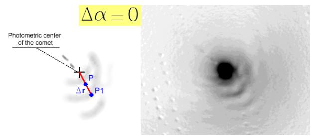
In the case
of zero rotational shifts, modifying the value of (delta r), we enhance the
contrast of all those details with a radial gradient of brightness with respect
to the false nucleus. The jets are no more visible, but we enhance halos,
spiral structures and shells of dust and gas that compose the inner layers of
the coma.
The
following image illustrates the comet C/1996 B2 (Hyakutake) taken at the
Observatory of Cavezzo on April 28 1996: it's the sum of 30 images of 10
seconds each.
1) ion tail; 2) tail disconnections; 3) false nucleus;
4) fountains; 5) shells.